A waterjet machine turns pressurized water into a precise cutting tool. It can shape steel, stone, glass, rubber, composites, and food products. The process creates little heat, which helps protect materials from burning, warping, or unwanted hardening. That difference matters when a clean edge is more valuable than speed alone.
Dr. Mohamed Hashish, widely recognized as a pioneer of abrasive-waterjet technology, once described the process this way: “The waterjet is a very versatile tool.” His observation reflects real workshop experience. A narrow stream exits a sapphire, ruby, or diamond orifice at extreme pressure. For harder materials, garnet abrasive joins the stream inside a mixing tube. The resulting jet can cut a detailed pattern while a CNC table guides its movement.
The machine is powerful, but it is not effortless. Operators must choose pressure, abrasive flow, nozzle distance, and cutting speed carefully. A small setting change can leave striations on a thick metal edge. Water can splash across the cutting area. Noise can become intense. Proper guarding, training, inspection, and hearing protection remain essential.
This guide explains how a waterjet machine works, from pump pressure to kerf formation. It also examines pure-water and abrasive systems, typical applications, operating costs, and maintenance concerns. Some explanations simplify complex physics. Real results vary with material, thickness, nozzle condition, and operator judgment. That limitation deserves attention. The machine is precise, but perfection still depends on preparation, measurement, and thoughtful control.
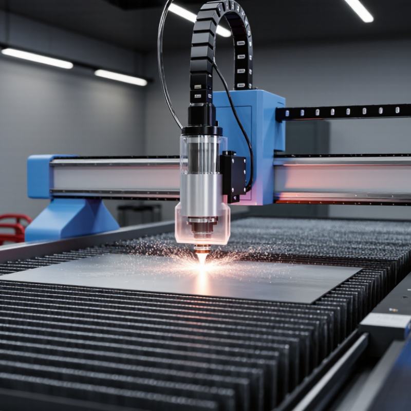
A waterjet machine is a computer-controlled cutting system that uses a narrow, high-pressure stream of water. It can cut metal, stone, glass, rubber, foam, and composite materials. The water exits through a very small nozzle, creating a focused jet with impressive cutting force. Pure water is suitable for softer materials. Harder materials usually require fine abrasive particles mixed into the stream. The process is cold, so it does not create a heat-affected zone around the cut.
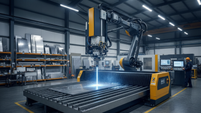
A typical waterjet machine includes a high-pressure pump, cutting head, abrasive feeder, motion table, and control system. The pump pressurizes the water, sometimes above 60,000 pounds per square inch. The cutting head then directs the jet along a programmed path. In abrasive cutting, a mixing tube combines water and particles before they reach the material. The table supports the workpiece and moves with careful coordination. It looks straightforward from outside. It is not.
Real cutting results depend on nozzle condition, water quality, material thickness, cutting speed, and operator settings. A worn mixing tube can widen the cut and reduce accuracy. Excessive speed may leave a rough edge or a slight taper. Slower movement often improves quality, but it increases production time. Experienced operators check test cuts before running valuable material. Even then, small imperfections can appear. That practical uncertainty deserves attention, especially when tight tolerances matter.
A waterjet machine uses high-pressure water to cut metal, stone, glass, and composites. Its core system contains a pump, intensifier, cutting head, nozzle, abrasive feeder, motion table, and catch tank. The pump supplies water, while the intensifier raises pressure, often near 60,000 psi in industrial systems. That pressure forces water through a tiny orifice.
The cutting head controls the jet’s shape and direction. Pure water suits softer materials, such as rubber or foam. Abrasive waterjets add fine garnet particles for steel, ceramic, and stone. The mixing chamber must remain stable. Small alignment errors can widen the kerf and reduce edge quality. The CNC motion table then guides the head along programmed paths. Underneath, the catch tank absorbs energy and collects spent abrasive.
Grand View Research reported that the global waterjet cutting machine market was valued at over USD 1 billion in 2023, with continued growth expected through 2030. This expansion reflects demand for cold cutting, which avoids heat-affected zones. Still, performance depends on more than pressure. Water quality, nozzle wear, abrasive flow, and operator calibration matter daily. In my experience, the nozzle is easy to overlook. It should not be. A worn nozzle can quietly turn a precise cut into an expensive rework. Industry guidance from the Water Jet Technology Association also emphasizes guarding, pressure control, and routine inspection. Perfect results are never automatic.
| Core Component | Primary Function | Typical Operating Data | Key Materials or Features | How It Supports Cutting |
|---|---|---|---|---|
| High-Pressure Pump | Raises ordinary shop water to the pressure required for cutting. | Common pressure range: approximately 3,000–6,000 bar (43,500–87,000 psi); flow is often about 2–8 L/min, depending on pump capacity and orifice size. | Intensifier or direct-drive design; high-strength seals, plungers, valves, and pressure tubing. | Converts mechanical energy into a narrow, high-velocity water stream. |
| Water Treatment and Filtration Unit | Removes suspended particles and controls dissolved minerals before water reaches high-pressure components. | Filtration commonly targets particles around 1–5 micrometres; reverse osmosis or deionization may be used where water hardness is high. | Sediment filters, carbon filters, water softeners, reverse-osmosis membranes, and monitoring sensors. | Reduces clogging, corrosion, and premature wear in the pump, orifice, and nozzle. |
| High-Pressure Tubing and Fittings | Transfers pressurized water from the pump to the cutting head. | Designed for working pressures commonly between 3,000 and 6,000 bar, with safety margins specified by the equipment manufacturer. | High-strength stainless steel tubing, cones, glands, swivels, and pressure-rated connections. | Maintains pressure while routing water safely through the machine. |
| Orifice | Converts the high-pressure water flow into a precise, focused jet. | Typical orifice diameter: approximately 0.15–0.35 mm, selected according to pressure, flow, and cutting requirements. | Synthetic sapphire, ruby, or diamond; the opening must remain circular and clean. | Determines jet diameter, water consumption, and the amount of energy delivered to the workpiece. |
| Abrasive Hopper and Metering System | Stores and feeds abrasive particles into the waterjet for cutting hard materials. | Abrasive consumption is commonly about 0.2–1.0 kg/min; garnet particle sizes frequently fall within approximately 80 mesh. | Sealed hopper, calibrated feed line, mixing chamber, and flow-control device; garnet is widely used as the abrasive. | Adds cutting particles to the water stream so the system can machine metals, stone, glass, and composites. |
| Mixing Chamber | Introduces abrasive into the focused waterjet through a controlled suction effect. | The chamber operates at the jet outlet and is matched to the water orifice and abrasive-feed rate. | Wear-resistant body, abrasive inlet, water orifice, and alignment components. | Creates a homogeneous abrasive-water stream before it enters the focusing tube. |
| Focusing Tube | Aligns and accelerates the abrasive-water mixture into a coherent cutting stream. | Typical internal diameter: approximately 0.8–1.2 mm; common length: about 75–100 mm. | Carbide or ceramic wear tube; concentric alignment is essential for cut quality. | Produces the narrow jet that removes material through erosion and high-speed abrasive impact. |
| Cutting Head and Motion System | Positions the jet and follows the programmed cutting path. | Abrasive cutting speeds vary widely, often from roughly 50 to 500 mm/min, depending on material, thickness, pressure, and quality target. | CNC-controlled X–Y axes; optional Z-axis height control and multi-axis tilt compensation. | Controls geometry, kerf direction, edge taper, and dimensional accuracy. |
| Cutting Table and Catcher Tank | Supports the workpiece and absorbs the jet after it passes through the material. | Water depth is commonly several hundred millimetres; table size depends on the machine and may range from compact formats to large industrial beds. | Slats, support grids, sacrificial supports, tank, drain, and abrasive sediment collection area. | Dissipates jet energy, limits noise and splash, and helps prevent damage below the workpiece. |
| CNC Control and CAD/CAM Software | Translates digital part geometry into machine movements and cutting parameters. | Controls feed rate, pierce sequence, cutting path, jet height, abrasive flow, and optional taper compensation. | Industrial controller, servo drives, position sensors, nesting tools, and toolpath software. | Coordinates the entire process for repeatable profiles and efficient material use. |
| Typical Cutting Characteristics | Defines what makes waterjet cutting suitable for varied materials and thicknesses. | Cold cutting process; kerf width is commonly about 0.7–1.2 mm, while maximum thickness depends strongly on material and required edge quality. | Minimal heat-affected zone; suitable for metals, stone, ceramics, glass, plastics, rubber, and composites. | Cuts by high-velocity erosion rather than melting, which helps reduce thermal distortion and heat-related metallurgical changes. |
Note: Operating values are representative industry ranges. Actual pressure, flow, abrasive consumption, cutting speed, kerf width, and maximum thickness vary with material, thickness, pump configuration, nozzle condition, and required edge quality.
Waterjet cutting begins with a digital drawing. The operator checks material thickness, tolerances, and the cutting path. A high-pressure pump then forces filtered water through a tiny orifice. WJTA technical guidance commonly references pressures near 60,000 psi for industrial cutting. The water leaves as a narrow, fast stream.
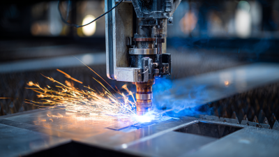
The next step adds abrasive grit when the material needs greater cutting power. Inside the mixing chamber, the water stream draws abrasive particles into the nozzle. The combined jet strikes the workpiece and removes material through erosion, not heat. This matters for steel, stone, glass, and composites because the process creates no heat-affected zone. A 2024 Grand View Research market report estimated the global waterjet cutting machine market at approximately 1.2 billion dollars in 2023, reflecting wider industrial adoption.
The nozzle then travels along the programmed path. Cutting speed depends on thickness, hardness, abrasive flow, and the required edge quality. A catch tank absorbs the remaining energy below the table. Operators monitor nozzle wear, pressure stability, and abrasive consistency during production. Small changes can affect taper and dimensional accuracy. That part is easy to underestimate. The machine may follow the file perfectly, yet poor calibration can still produce a disappointing edge. Experienced technicians often make a test cut first, measure it, and adjust the program before releasing the full sheet.
A waterjet machine uses a high-pressure stream of water to cut materials. Abrasive waterjets add fine mineral particles when cutting hard materials such as steel, stone, glass, and ceramics.
First, a pump pressurizes the water, commonly within the 2,000–6,000 bar industrial range. The pressurized water passes through a small orifice, converting pressure into a very fast jet. For abrasive cutting, the jet draws abrasive particles into a mixing chamber before the stream reaches the material. The focused jet then erodes the workpiece along a programmed cutting path without generating a heat-affected zone.
What Is a Waterjet Machine and How Does It Work?
Main Types of Waterjet Machines
A waterjet machine forces water through a tiny orifice at extreme pressure. Industrial systems commonly operate between 30,000 and 90,000 psi. The narrow stream removes material through erosion, not heat. That matters when cutting aluminum, stone, glass, rubber, or layered composites. The machine leaves no heat-affected zone, although poor setup can still produce taper or a rough lower edge.
Pure waterjet machines use only pressurized water. They suit foam, textiles, insulation, food products, and thin plastics. Abrasive waterjets mix water with fine garnet after the nozzle. This added cutting force handles steel, titanium, ceramics, and thick stone. The difference is practical. Pure water protects soft surfaces, while abrasive cutting expands material capability. It also increases consumable use and maintenance.
Three-axis machines cut flat profiles with straightforward programming. Five-axis systems tilt the cutting head and compensate for taper, supporting bevels and complex 3D parts. Micro-waterjet machines use a smaller stream for delicate, high-precision components. According to Grand View Research’s 2024 analysis, the global waterjet cutting machine market was valued at approximately 1.3 billion dollars in 2023, with abrasive systems representing the dominant application segment. That figure signals strong industrial adoption, but machine choice is rarely perfect. Shop trials still matter. A technically powerful system may waste time on thin, fragile material.
A waterjet machine cuts material with a focused stream of water, often mixed with abrasive grit. A high-pressure pump sends water through a tiny orifice, creating a fast, narrow jet. The cutting head follows a programmed path while software controls speed, height, and direction. Unlike thermal tools, it produces little heat-affected distortion. This helps when a cut edge must remain stable and clean. It is not magic. The process still needs careful setup.
Operators commonly cut steel, aluminum, copper, stone, glass, ceramic, rubber, foam, and layered composites. Pure water can handle softer materials, while abrasive waterjet cutting suits harder sheets and slabs. In fabrication shops, it produces brackets, panels, gaskets, machine parts, and architectural inlays. Contractors also use it for renovation work where sparks or intense heat could damage nearby surfaces. Material thickness changes everything. A thick plate may require slower travel, more abrasive, and a second finishing pass.
The main advantages are narrow kerfs, low mechanical force, and flexible shape cutting. One setup can create holes, curves, and internal corners without custom dies. It also avoids many fumes associated with thermal cutting. Accuracy depends on nozzle condition, calibration, material stability, and operator judgment. Waste can still occur when nesting is poor or abrasive flow is excessive. For that reason, test cuts and measured inspection remain essential. The machine is powerful, but its results are only as reliable as the process behind them.